The Determination of Convective Heat Transfer Coefficents on Quenching Monofilament
18 June 2019
Tags : composite,
composite reinforcement,
efficiency,
Fiber Production,
heat transfer,
Kordsa,
monofilament,
production process,
R&D,
Reinforcer,
the reinforcer
Kordsa is a leader in the global tire cord industry. Kordsa’s R&D center reseach focuses on the improvement of existing products and new product development as well as research on new materials. Before the R&D center was established, new product developments were carried out by trial and error and process experience. It is almost impossible to find optimum solution for a product through trial and error. So these trials took too much time and too much expense. Moreover, the response time in developing new products for customers will be shorter and accordingly Kordsa will be able to better serve its customers.
The purpose of this study is to determine a convective heat transfer coefficent in order to understand the temperature profile of a filament in the cooling process. A functional model will have many benefits to the textile industry over the long term. Some of these benefits include new product development in a shorter time and at less cost, the optimization of equipment and processes and better service to customers.
Fiber Production
Synthetic fibers can be produced through the following steps: polymer synthesis, spinning (the extrusion, solidification, and deformation of the spinning line or filament), drawing (used to increase the degree of orientation and improve the tensile strength, modulus of elasticity, and elongation of fibers), heat treatment (crystallization), and textile processing (twisting, dyeing, etc.)
Spinning means a different thing for synthetic fibers. Spinning for natural fibers means that twisting of short fibers so that they gain continuous filaments. However, the spinning of synthetic fibers means the production of continuous filaments by any means. The yarn is made by twisting many filaments together. Spinning can also be called continuous drawing. The word “spinning” is commonly used in textile industry. A fiber is the fundamental unit of textiles, and it is defined as a material which has a length to diameter (or width) ratio of about 100. There are two types of fibers, natural and synthetic, and the aim of fiber spinning is to produce continuous filaments of a uniform diameter with the physical properties desired by the end user
Spinning can be performed with three different techniques: melt spinning, dry spinning, solution wet-spinning, phase separation spinning, emulsion spinning, gel spinning, and reaction spinning. Melt spinning is the easiest and most economical technique of the three. It involves only heat transfer and extensional deformation.. Polyamides (nylons), polyesters, polystyrene, polyolefins and inorganic glasses are typical examples of melt spun polymers.
A typical example of the melt spinning process is shown in Figure 1. The extrusion through a spinneret (or die), the die swell (relaxation of the elastic stress of the polymer), the quenching of the filaments, the solidification of the polymer, and the cold drawing from the solidification point are all shown below.
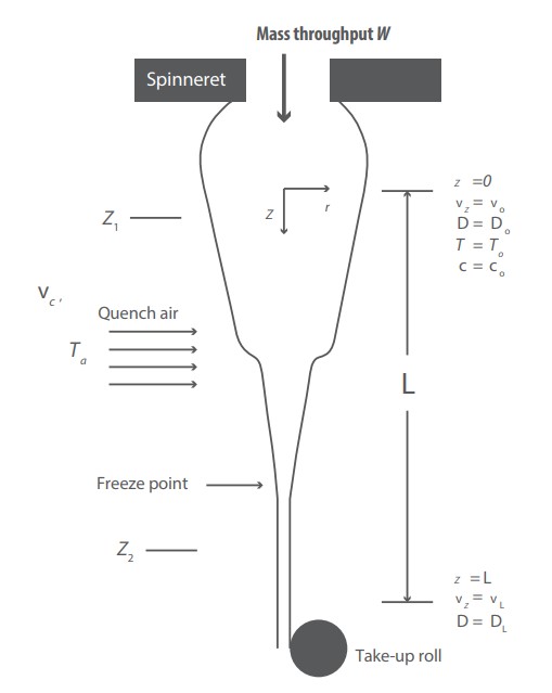
Figure 1: Melt Spinning
The Quenching Process
Heat transfer (or heat) is thermal energy in transit due to a spatial temperature difference. The transfer of energy as heat is always from a higher-temperature medium to a lower-temperature one, and heat transfer stops when the two mediums reach the same temperature. Heat can be transferred in three different modes: conduction, convection, and radiation. The heat transfer mechanisms used in this study are convection and radiation. These mechanisms are formed on the wires in the wind tunnel environment.
The regional convective heat flux of a fluid over a surface and total heat transfer are expressed as:
QConv. = h.π.D.L.(TS -T∞ )
Radiation is the emission or transmission of energy in the form of waves or particles through space or through a material medium such as alpha radiation (α), beta radiation (β), and neutron radiation, electromagnetic radiation. Its equation is expressed as:
QRad. = ε. σ. π.D.L ( TS 4 - TSURR4 )
Heat transfer is a function of Reynolds Number,
Re=ρ.V.L / µ
and the Prandtl Number,
Pr=µ.cp / k
where p is the fluid density, V is a bulk velocity, u is dynamic viscosity, k is the fluid conductivity, and cp is the specific heat. L is a characteristic length, such as a diameter. Reynolds number is the ratio of the forces of inertia to the forces of viscosity. The Prandtl Number is a dimensionless number approximating to the ratio of momentum diffusivity to thermal diffusivity. In heat transfer at a boundary (surface) within a fluid, the Nusselt number (Nu) is the ratio of convective to conductive heat transfer across (normal to) the boundary.
Nu=h.L / k
This equation gives us the Nusselt numbers for various flow conditions. The Nusselt number is added into the equation and the heat transfer coefficent h is found. There are many correlations that predict the heat transfer coefficent in the literature.
| Equation for Nu-number (Only parallel flow) |
References and conditions |
| 3.0Re-0.22 |
Golzar |
| 0.25 + 0.15Re0.36 |
Zieminski |
| 0.325Re0.3 |
Glicksman |
| 0.53Re0.33 |
Copley |
| 0.42Re0.334 |
Kase, Matsuo |
| 0.28(Re2 ) 0.17 |
Brünig |
| 0.16(Re)0.50 |
Ohkoshi |
Table 1: Relationships of Reynolds and Nusselt Numbers in melt spinning
Experimental Study
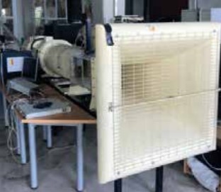
Figure 2: Wind Tunnel Test Apparatus
A Wind Tunnel Test Apparatus is shown in Figure 1. The experimental test apparatus comprises a tunnel, fan, power supply, digital multimeter, flow meter, frequency converter and wires which are of diameters between 0.2 mm to 1.0 mm. These are used to represent monofilament yarn.
An AATech-ADM 3303 DD model power supply is used for heating the wire and to convert electric current from source to the correct voltage, current, and frequency to power the load. An AATech-ADM 3055 model digital multimeter is used for the measurement of voltage and to obtain the temperature of the wires. The fan sucks air from the medium to the tunnel. Air passes over the wires and cools them. The air flow rate is adjusted with a frequency converter and is measured with Testo 435 model flow-meter.
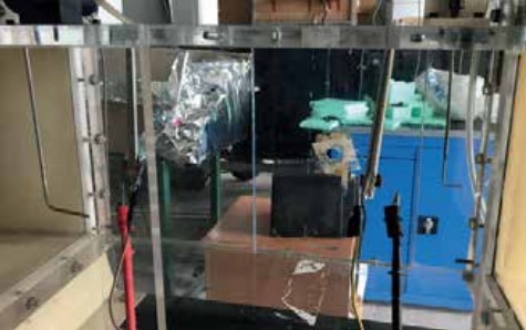
Figure 3: Wire and wire holder for parallel flow
A wire holder is used to keep the wires stable within the air flow and an insulation material is used to prevent current flow. The position of the cylinder inside the wind tunnel is very important. The cylinder is positioned longitudinally at a 0 degree angle within the parallel flow. Tests are carried out according to experimental parameters that are given in Table 2.
| |
Min Value |
Max Value |
| Air velocity (m/s) |
0,5 |
5 |
| Diameters of wires (mm) |
0,2 |
1 |
Table 2
Results and Discussions
The results showed that a higher diameter value of wire provides a lower forced convection heat transfer for the same air velocity. Under the same experimental conditions and with the same wires, the convective heat transfer coefficent increases with air velocity, which is seen in Figure 4.
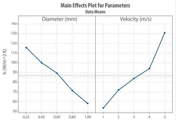
Figure 4: Main Effects Plots for Parallel Flow
Figure 5 shows that the Nusselt and Reynolds numbers change when they are calculated from experimental results for parallel flow. The experiments were carried out in the range of Reynolds numbers from 9 to 275, with an r2 value of 0.93. The convective heat transfer coefficents were found from 24 to 160 W/m2.K. The results were compared with Golzar, Ohkoshi, Zieminski, Glicksman, Copley, Brünig and, Kase and Matsuo’s correlations
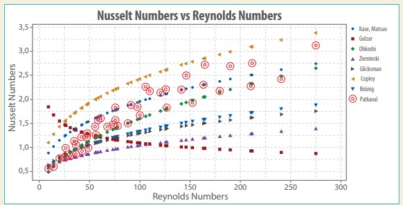
Figure 5: Reynolds and Nusselt Numbers for Parallel Flow
The Patkavak correlations of the Nusselt numbers for the present data can be expressed as follows;
Nu = 0,1516Re0,5368for parallel flow, 9
The present results are in good agreement with literature and they are in same range as these Reynolds numbers. These studies will be continued at Yildiz Technical University’s laboratory to obtain convective heat transfer coefficents underwater in liquid isothermal bath cooling. Afther these studies, Kordsa will use their own formulas to further analyze the cooling process of yarn.
Tags : composite,
composite reinforcement,
efficiency,
Fiber Production,
heat transfer,
Kordsa,
monofilament,
production process,
R&D,
Reinforcer,
the reinforcer